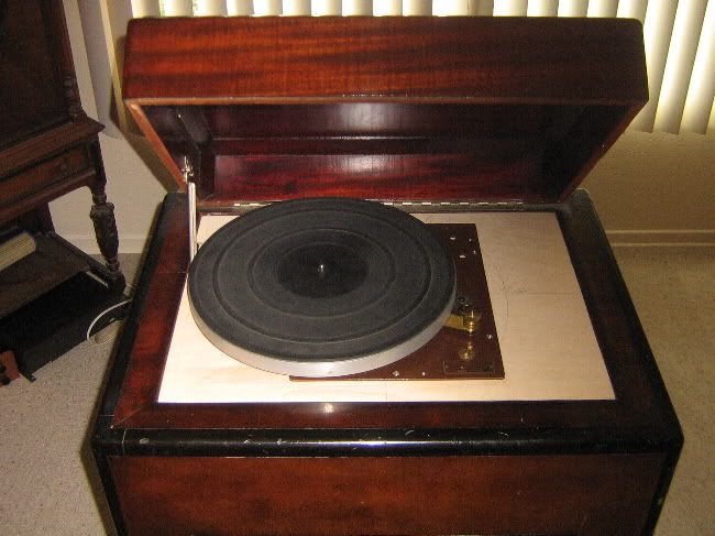
the plinth'ing begins,....
I'm going to use five stacked layers of .70" / 18mm HomeDespot birch ply, as a suspended plinth, plus, a base shelf layer that is attached to the cabinet. I've yet to find a single void after making tons of cuts - fine wood. This is my second plinth out of it now.
I'm going to build in a suspension system, utilizing 1.5" Mighty Morpin Power Rangers Super-Balls from BigLots that cost a whopping $2 for two two-packs.
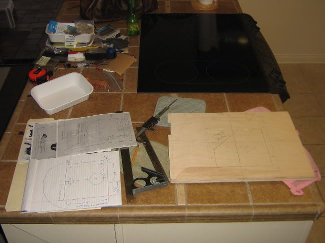
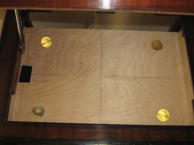
let the cipherin' begin;
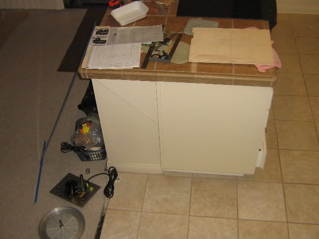
the end of the kitchen peninsula counter is where I do my thinking and drawing:
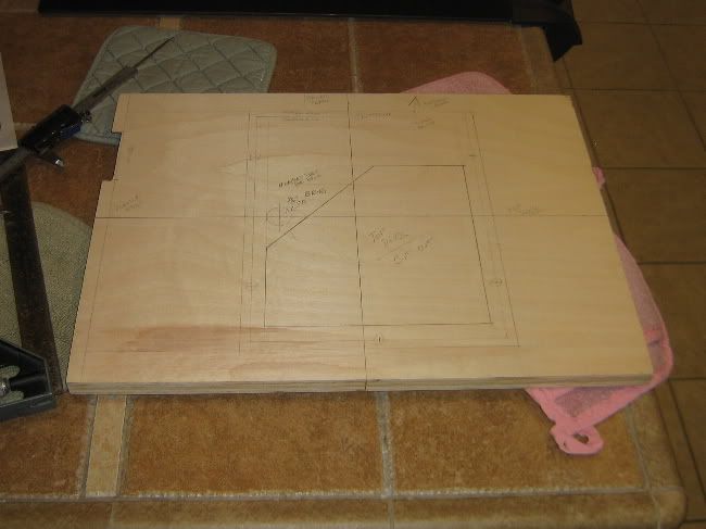
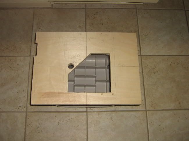
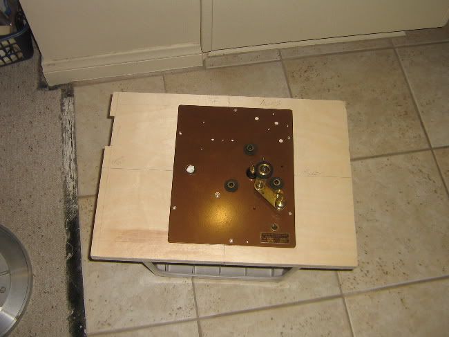
cut-out top deck layer (layer 5):
On the inverted stool plinth:
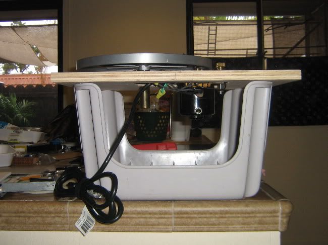
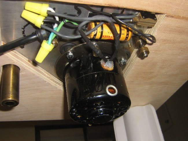
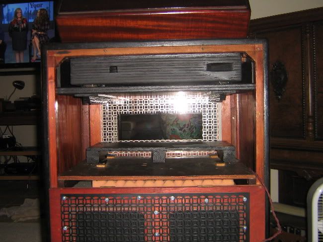
the underpinnings:
in the cabinet, with the rest of the layers cut to match:
I'm going to use a metal sheet over the wood, of either real copper, or, hammered copper painted on aluminum. The wood top deck will be painted black, lacquer black gloss, to match the trim, with the metal top deck mounted over it.
The arm wants to fit half on the original top plate, and half off of it. So I'm going to have to rig an arm board extension to the side of the top plate to carry half the tonearm base, and level it.
Next up,... the backside development, and the Mighty Morphin power Range Superball suspension! I know y'all are dying to see this one ::laughs maniacally::
plinth suspension test boards, with the mighty morphin power rangers:
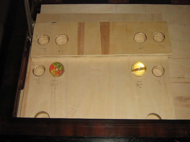
The two boards, ^^, represent the base shelf layer that is attached to the cabinet and, the turntable plinth, which is supposed to be suspended and isolated from the cabinet.
I found that the Lenco spring suspension plinth eliminated resonant cabinet feedback, so I decided to incorporate a suspension system within this plinth build.
My wife found some superballs at a clearance store chain that were an inch and a half in diameter.
The boards were utilizing various levels of contact and containing of the balls. I finally settled on a clear pass-thru hole for the bottom of the suspension layer, and a capturing smaller diameter at the upper layer.
The bottom layer depends on the ball riding on the tangential apex contact of the curve of ball and supporting surface on the bottom, and, the plywood rim around its center diameter (1.40" ball diameter and 1.5" hole saw cutout in .70" plywood). The top layer solidly captures the ball around a ring about 3/4 high on the ball (a 1" hole, with rounded over edge).
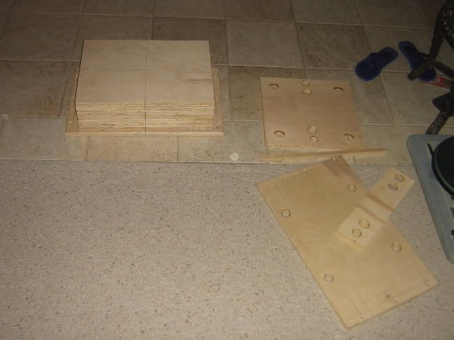
Here is the stack of layers of plinth plywood leaves on the base, testing the suspension - trying for overload:
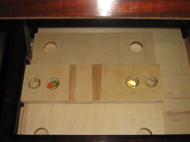
Here is a view of the plinth in early fitting stages, with the superballs in place:
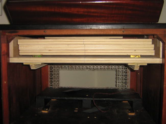
The staggered offset of the ply layers centerline, above ^^, is due to the lid prop cut-outs not being done yet. I took the picture before I'd cut them out. So there is the staggered offset present; which has since been corrected.
Base layer with suspension bearing balls:
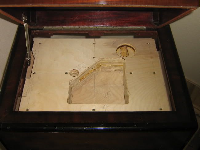
layer 3 - now laminated to b1 and b2, with tonearm cutout base structure. THe keyhole at the bottom is to pass a cable through to the tonearm base mounting plate:
plinth painted flat black.
The base layer and b1,2,3 are separate from the 4th and 5th top layers. They are all screwed together into a monolith, but need to be separate for assembling.
There are five total layers of minimal cut-away layers as a base.
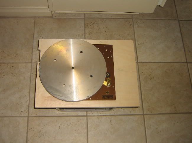
Now with the addition of a solid copper top plate that the TT mounts to:
Up next,... the tonearm mounting.
I've got to level the arm area, as the arm wants to hang off of the original top plate. The OR top plate is 1/8" thick, which is easy enough to match. Then I want to add another thin layer to cover the OE top plate holes and bridge over onto the additional extension of the top plate (the 1/8" elevation offset addition).

 Topic: Finished Project: Building My Monaural Playback System (Read 18178 times)