Become a Site Supporter and Never see Ads again!

Author Topic: OsPre - Open Source Preamp  (Read 12101 times)

0 Members and 1 Guest are viewing this topic.

Offline fivefishdiy

  • Trade Count: (0)
  • Taperssection Regular
  • **
  • Posts: 193
  • Gender: Male
    • FiveFish Studios
OsPre - Open Source Preamp
« on: June 28, 2008, 04:33:25 PM »
In another thread, a member suggested that it will be cool if information and sharing is more open (with regards to schematics). 

That got me thinking and think it will be a neat experiment.  So I'm submitting "The OsPre"... the Open Source Preamp <whatever that means>

This is just a quick sketch done within the last hour, there are no values on the components, and it's not tested yet.  If anybody want to contribute, suggest values, give values, create a shopping list of parts, etc... you're welcome to do it.

If you think there are better choices in opamps, feel free to suggest... I just picked this opamp from the TI website just browsing at the specs.

Goal:
2 channel simple preamp  (i.e. preamp as in signal conditioning, more gain.)
Output: Stereo jacks unbalanced
Voltage supply: 9V or more
....
blah blah blah
....
<the rest... come up with it, or contribute and share the schematic >
....


Here's the initial seed file.


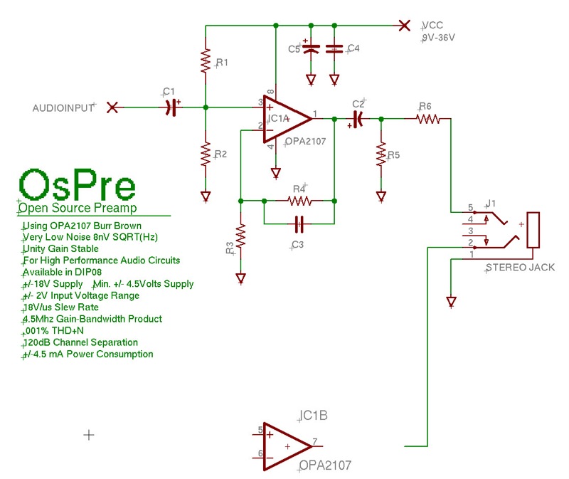
Some brief description:
C1, C2 = AC coupling capacitors
R1, R2 = for creating a virtual ground for single-ended supply operation
C4, C5 = PSU bypass capacitors
R6 = short circuit protection, in case output of opamp got shorted
R5 = load
R3, R4 = for setting gain of opamp 
C3 = bypass capacitor
i.e.  6dB = 2x voltage ratio
      20dB = 10x voltage ratio
      40dB = 100x voltage ratio
IC1, IC2 = opamp
J1 = stereo jack output

Not included here:
- circuit for biasing electret mics, or phantom power for condenser mics
- no high pass filters or any of that
- no leds or vu metering

Let's see how far we get with this... okay, people... start contributing!

SC-1 Mic Preamp Kits... www.fivefishstudios.com
Photo Rig: Canon EOS30D, 70-200 f4L, 24-105 f4L, 50mmf1.8, 10-22mm Wide angle, Sigma 200mm Macro, Harddisk CF card reader/backup
Video: Sony HDV HDR-HC5

Offline illconditioned

  • Trade Count: (9)
  • Needs to get out more...
  • *****
  • Posts: 2997
Re: OsPre - Open Source Preamp
« Reply #1 on: June 28, 2008, 05:08:53 PM »
^^ Very nice.  Thanks for the post.

I think this is pretty similar to Chris Church's preamp.  I have not seen the insides, but I think he uses a Burr Brown chip, but maybe something more suitable for audio, like the OPA2227 or OPA2228.  I honestly don't know if the various chips matter, except for the powering requirements.

Many here will end up buying Church's or another similar pre, which are great value for the money, but I encourage anyone interested in tinkering to try out this circuit for themselves.  It is a good place to get started.  Also, I recommend the Yahoo group "micbuilders" that is full of tinkerers, both for preamps and various projects with bare mic capsules.

Some suggestions:

- use a "rail splitter" chip, eg., TLE2426, instead of a resistor divider to get "virtual ground".  Less current drain on battery, and more precise.  See http://tangentsoft.net/elec/vgrounds.html for a nice description of rail splitters.  (Context is headphone amps, I believe, but circuits are same for preamps.)

- I have built a circuit with the TLE chip and a hot new opamp, LM4562, from National Semiconductor.  I posted a schematic way back, I'll try to dig it up again, but basically the same as this design, except for the rail splitter.  This is supposedly the best audio opamp now.  Runs on pretty low voltages too (like 5V single supply).  I've also used a surface mount version of this chip (SOIC8) to modify a Fostex FR-2LE.  It comes in DIP8 and SOIC8 and is approx $5 from Digikey.com.

  Richard
Please DO NOT mail me with tech questions.  I will try to answer in the forums when I get a chance.  Thanks.

Sample recordings at: http://www.soundmann.com.

Offline fivefishdiy

  • Trade Count: (0)
  • Taperssection Regular
  • **
  • Posts: 193
  • Gender: Male
    • FiveFish Studios
Re: OsPre - Open Source Preamp
« Reply #2 on: June 28, 2008, 07:44:59 PM »
Yeah, I wouldn't run this circuit on too much gain. For one, the input is unbalanced. 2nd, unless the supply voltage is huge, you'd get into headroom clipping.

If the input is balanced and we can use CMRR to our advantage, it may be possible to pump up the gain.

The 2 resistor virtual ground trick won't be so bad. (2) series 10K resistor on 9V supply is only 0.45 mA.  (0.04 Watts).  Thing is if you add another chip and buffer for that, the power savings may be a wash (or you'll use up more power than 2 resistors) since the additional chips will have to consume power. Also, cost is higher since you're adding to the parts count, and bigger PCB area, bigger case, etc.

Yeah, R4 can be made variable with a series limiting resistor. But I'm thinking if you're mounting a pot through the panel via flying wire leads, that would be a noise/RFI magnet (at that critical junction in the circuit). So I'm thinking just set to your max gain (20dB, or 30dB) via a fixed resistor, then just use a trimmer pot as a volume on the input.


SC-1 Mic Preamp Kits... www.fivefishstudios.com
Photo Rig: Canon EOS30D, 70-200 f4L, 24-105 f4L, 50mmf1.8, 10-22mm Wide angle, Sigma 200mm Macro, Harddisk CF card reader/backup
Video: Sony HDV HDR-HC5

Offline Church-Audio

  • Trade Count: (44)
  • Needs to get out more...
  • *****
  • Posts: 7571
  • Gender: Male
Re: OsPre - Open Source Preamp
« Reply #3 on: June 28, 2008, 08:07:16 PM »
Yeah, I wouldn't run this circuit on too much gain. For one, the input is unbalanced. 2nd, unless the supply voltage is huge, you'd get into headroom clipping.

If the input is balanced and we can use CMRR to our advantage, it may be possible to pump up the gain.

The 2 resistor virtual ground trick won't be so bad. (2) series 10K resistor on 9V supply is only 0.45 mA.  (0.04 Watts).  Thing is if you add another chip and buffer for that, the power savings may be a wash (or you'll use up more power than 2 resistors) since the additional chips will have to consume power. Also, cost is higher since you're adding to the parts count, and bigger PCB area, bigger case, etc.

Yeah, R4 can be made variable with a series limiting resistor. But I'm thinking if you're mounting a pot through the panel via flying wire leads, that would be a noise/RFI magnet (at that critical junction in the circuit). So I'm thinking just set to your max gain (20dB, or 30dB) via a fixed resistor, then just use a trimmer pot as a volume on the input.


I dont want to get into to much details because well its how I make a living.. But my preamp is based on the OPA2227PA + 741 opamp as a rail split. I can get a noise floor of -99 dbA at full gain of 20db and current draw of less then 8mA headroom is -10 db at less then 0.007% distortion at 1k. I have another supply that seperates my vitual ground on the input so I can feed 8 volts to power the mics connected to it. Its a pretty good circuit. The new preamp we are working on is much more advanced. But you are on the right track 30 db is very hard with this type of circuit sure you can get 30 db but the noise floor like you mentioned is much higher. And really unusable I did try a second opamp as well as a buffer but the current draw was too high. I Think the key is some fets in the front end a simple two transistor front end with say 10 db of gain then going into the opamp might be a simple solution to get more gain out of the basic single opamp circuit.. If it can have enough headroom in the front end then the "volume" can be put after the first stage. I found using resistors as a spliter worked ok until you need bias voltage from the same positve rail then you end up unbalancing the circuit and although these opamps will work with an unbalanced rail the headroom is not so good.

Chris


« Last Edit: June 28, 2008, 08:09:30 PM by Church-Audio »
for warranty returns email me at
EMAIL Sales@church-audio.com

Offline Church-Audio

  • Trade Count: (44)
  • Needs to get out more...
  • *****
  • Posts: 7571
  • Gender: Male
Re: OsPre - Open Source Preamp
« Reply #4 on: June 28, 2008, 11:26:22 PM »
Here are some good reads from TI on these topics:

This one is WAY LONG, but if you make it through, you'll be an expert!

http://focus.ti.com/analog/docs/techdocsabstract.tsp?familyId=57&abstractName=slod006b

Edit:  well, I thought this covered the single-supply issues we've been talking about, it doesn't quite, but it has lots of practical circuits--EQ too!

http://focus.ti.com/lit/an/sloa058/sloa058.pdf

Here's the virtual ground discussion I was remembering:

http://tangentsoft.net/elec/vgrounds.html

Let's analyze their sample resistive divider circuit in terms of a mic amp rather than a headphone amp.  OK, instead of a gain of 10, let's crank it up to 30 (for our 30dB gain).  But instead of a 32 ohm headphone, we just need to drive, worst case, a 600 ohm load.  That makes our DC across the load of 31mV result in rail offset of about 0.2V with 10K ohm divider resistors.  That should be tolerable, but it does illustrate why 30dB is a good practical limit for this circuit, even with a faster opamp than I use.

A couple of random notes:  the gain of 30 giving us (about) 30dB was just a one-time coincidence, like -40 Fahrenheit = -40 Celsius.  The formula for voltage gain is dB = 20*log(gain).

Also, on the topic of opamps and speed, the most important stat is called "gain bandwidth product", or GBW.  Presuming we want an audio bandwidth of 20kHz, divide GBW by that figure, and that's your maximum possible gain from that opamp.  But most people think you don't really want to stress that limit too much, so leave some cushion.

Also there is slew rate; if you think about a 20kHz signal, it goes from positive to negative peak in 25usec.  So if your signal is 1V peak, then you need a minimum slew rate of .08V/usec.  Of course, you want higher headroom that that, let's say you are using a 9V battery, and give a little for the power rails and a half-dead battery, say 6V peak to peak.  OK, .5V/usec.  Again, some cushion is desired.  I've read very well respected designers suggest 5x required slew rate.  The good news is that's a pretty easy spec for most modern opamps.

(always helpful for somebody to check my math)

Beware of the superfast opamp though--these can be testy about oscillating at frequencies you can't hear, but will degrade performance greatly.  If you are building a hobby circuit without the benefit of an o-scope, stick to tried and true opamps and mind the need for bypass capacitors and 0.1uF caps at the power rails as mandated in the opamp's datasheet.

I like OPA2134 for no-fuss no-muss performance.

I was useing the 2134 but I found the current draw higher then the opa2227 and not really any major performance gain. At least in my circuit.
for warranty returns email me at
EMAIL Sales@church-audio.com

Offline Church-Audio

  • Trade Count: (44)
  • Needs to get out more...
  • *****
  • Posts: 7571
  • Gender: Male
Re: OsPre - Open Source Preamp
« Reply #5 on: June 29, 2008, 08:59:04 AM »
Yeah, that's probably a toss-up in this circuit.  OPA2134 is faster but noisier, and 1mA thirstier.  But you can't really use the speed with a 9V battery.  On the other hand, you can't realize OPA2227's low noise performance with a relatively high-impedance single-ended design.

Well I am still looking for the magic chip :) Hi gain low noise low current but I dont really know if its out there.
for warranty returns email me at
EMAIL Sales@church-audio.com

Offline fivefishdiy

  • Trade Count: (0)
  • Taperssection Regular
  • **
  • Posts: 193
  • Gender: Male
    • FiveFish Studios
Re: OsPre - Open Source Preamp
« Reply #6 on: June 29, 2008, 04:53:39 PM »
20dB-30dB is not what I consider high-gain.  That's on the low end of the gain scale.

About low current consumption, well, that's splitting hair.  The OPA134/2134 is 4mA, and the OPA2227 is 3.8mA.  Big deal. Adding a single LED to the circuit would blow that savings out of the water!

I don't think there is a need to look for the "magic chip." Truth is any of the opamps listed above (and probably hundreds other model) can be used in this circuit just fine and will perform just as well compared to each other. Even the lowly NE5532/5534 will work here. There's nothing complicated about amplifying line level signals 10x more.

The real limitation in this particular circuit/design is the single-ended input (i.e. unbalanced input). This will be the limiting factor in how much gain is practical without amplifying the accompanying noise too much. This just limits the applications  of this preamp design... i.e. not good for dynamic and ribbon mics that need high gain (48dB and above... 60, 66dB or more).

Now, if you put in an electret mic at the inputs and keep the wires short, or even incorporate it into the same PCB, then this circuit will be just fine. Even then, there is no CMRR and it will be noise susceptible.

If the user isn't expecting too much, the above OsPre preamp is just fine for what it's intended... small gain, line-level amplification.


SC-1 Mic Preamp Kits... www.fivefishstudios.com
Photo Rig: Canon EOS30D, 70-200 f4L, 24-105 f4L, 50mmf1.8, 10-22mm Wide angle, Sigma 200mm Macro, Harddisk CF card reader/backup
Video: Sony HDV HDR-HC5

Offline illconditioned

  • Trade Count: (9)
  • Needs to get out more...
  • *****
  • Posts: 2997
Re: OsPre - Open Source Preamp
« Reply #7 on: June 29, 2008, 05:15:43 PM »
20dB-30dB is not what I consider high-gain.  That's on the low end of the gain scale.

You're right.  But this is plenty for the concert taper.  Often combining both "hot" mics and loud volumes, you don't even need a preamp.  For example, I run Beyerdynamic MC930 directly into line in on Edirol R09!  What is important in the field is battery power, and either phantom or miniplug input, depending on the mics.   I bet 20-30dB is enough for most, except for acoustic/classical stuff.

Quote
I don't think there is a need to look for the "magic chip." Truth is any of the opamps listed above (and probably hundreds other model) can be used in this circuit just fine and will perform just as well compared to each other. Even the lowly NE5532/5534 will work here. There's nothing complicated about amplifying line level signals 10x more.
I've found some of the newer chips, like LM4546 are great because they can run on lower voltages, like +5V.  Great for modding gear, like Fostex FR-2LE , Edirol UA5, etc as well, where the internal voltages are often very low.

Quote
Now, if you put in an electret mic at the inputs and keep the wires short, or even incorporate it into the same PCB, then this circuit will be just fine. Even then, there is no CMRR and it will be noise susceptible.

If the user isn't expecting too much, the above OsPre preamp is just fine for what it's intended... small gain, line-level amplification.
Exactly.

  Richard
Please DO NOT mail me with tech questions.  I will try to answer in the forums when I get a chance.  Thanks.

Sample recordings at: http://www.soundmann.com.

Offline Church-Audio

  • Trade Count: (44)
  • Needs to get out more...
  • *****
  • Posts: 7571
  • Gender: Male
Re: OsPre - Open Source Preamp
« Reply #8 on: June 29, 2008, 06:37:57 PM »
20dB-30dB is not what I consider high-gain.  That's on the low end of the gain scale.

About low current consumption, well, that's splitting hair.  The OPA134/2134 is 4mA, and the OPA2227 is 3.8mA.  Big deal. Adding a single LED to the circuit would blow that savings out of the water!

I don't think there is a need to look for the "magic chip." Truth is any of the opamps listed above (and probably hundreds other model) can be used in this circuit just fine and will perform just as well compared to each other. Even the lowly NE5532/5534 will work here. There's nothing complicated about amplifying line level signals 10x more.

The real limitation in this particular circuit/design is the single-ended input (i.e. unbalanced input). This will be the limiting factor in how much gain is practical without amplifying the accompanying noise too much. This just limits the applications  of this preamp design... i.e. not good for dynamic and ribbon mics that need high gain (48dB and above... 60, 66dB or more).

Now, if you put in an electret mic at the inputs and keep the wires short, or even incorporate it into the same PCB, then this circuit will be just fine. Even then, there is no CMRR and it will be noise susceptible.

If the user isn't expecting too much, the above OsPre preamp is just fine for what it's intended... small gain, line-level amplification.


I dont call 20 db high gain either :) But its hard to squeeze much more with a simple voltage divider circuit with out running into limitations of headroom and current. And actually in my tests even though the specs might indicate otherwise. I have measured the OPA2134 Vs the OPA2227PA and in my circuit the difference was not .2mA it was more like 5 mA and when your running from a single 9 volt 5 mA difference is alot.
Chris
for warranty returns email me at
EMAIL Sales@church-audio.com

Offline fivefishdiy

  • Trade Count: (0)
  • Taperssection Regular
  • **
  • Posts: 193
  • Gender: Male
    • FiveFish Studios
Re: OsPre - Open Source Preamp
« Reply #9 on: June 29, 2008, 10:14:38 PM »
The datasheet current specs are correct. But those readings are taken at +/-15V Vs, as noted by the specification conditions.

If you do run it at a lower voltage, say from a 9V battery, current usage will have to climb to keep the same Power equation (V x I).

I don't have experience with the 2227, but I do use the OPA134 (the single version of the OPA2134).

Bottomline is the OsPre design can't go any further... apart from upgrading and using "newer" opamps. And even that, the benefits that newer chips bring are questionable, given the limited supply voltage and unbalanced design.
SC-1 Mic Preamp Kits... www.fivefishstudios.com
Photo Rig: Canon EOS30D, 70-200 f4L, 24-105 f4L, 50mmf1.8, 10-22mm Wide angle, Sigma 200mm Macro, Harddisk CF card reader/backup
Video: Sony HDV HDR-HC5

Offline fivefishdiy

  • Trade Count: (0)
  • Taperssection Regular
  • **
  • Posts: 193
  • Gender: Male
    • FiveFish Studios
Re: OsPre - Open Source Preamp
« Reply #10 on: June 30, 2008, 10:43:12 AM »
Quote
Bottomline is the OsPre design can't go any further
Quote
That's a strange statement to make, in light of this being open source.

What I meant is the topology of the current design. i.e. being unbalanced and the limited supply voltage. Not unless that is scratch and we use a different topology.

No I haven't built the OsPre design, no time yet. Maybe someday I will. Right now, we're just bouncing ideas.

Quote
C4 should be specified as quite close to the opamp V+ and V- supply on the PCB; that's not clear in your schemo.
Yes, that's a given in my book. But I should put a note about that for other builders.

Thanks for posting your schematics. Do you have a working proto?

Well, I really don't know how to handle open source project so I'm not sure what's the next step. As I said earlier, this is just an experiment. Does somebody want to draw a second revision of the circuit and incorporate additions? protection diodes, make R4 variable, etc...
SC-1 Mic Preamp Kits... www.fivefishstudios.com
Photo Rig: Canon EOS30D, 70-200 f4L, 24-105 f4L, 50mmf1.8, 10-22mm Wide angle, Sigma 200mm Macro, Harddisk CF card reader/backup
Video: Sony HDV HDR-HC5

Offline bugg100

  • Trade Count: (0)
  • Taperssection All-Star
  • ****
  • Posts: 1015
  • Gender: Male
Re: OsPre - Open Source Preamp
« Reply #11 on: June 30, 2008, 02:41:29 PM »
What happens to this project if it is designed for 18v via 2 9volt batteries?

Offline Scooter

  • Trade Count: (2)
  • Taperssection All-Star
  • ****
  • Posts: 1770
  • Gender: Male
Re: OsPre - Open Source Preamp
« Reply #12 on: June 30, 2008, 04:15:18 PM »
.
MBHO 603a(ka200n/ka500hn) >
R-44, or H120

LMA Recordings

Offline illconditioned

  • Trade Count: (9)
  • Needs to get out more...
  • *****
  • Posts: 2997
Re: OsPre - Open Source Preamp
« Reply #13 on: July 02, 2008, 01:07:50 AM »
Some lessons learned:
 
We should be humble about our building capabilities.  In the past I built a +15dB circuit similar to above.  I decided to try it out, and hey, it distorts on loud signals.  I don't have the equipment or patience to figure out the circuit problem.
  *** So, I would be happy to pay someone else, like Fivefish or Chris Church, to build this (and guarantee/service/test it).  But I would much rather know what is inside.  And it is also cool knowing (serious) DIY types can really build the thing.

Another point learned, I don't really *need* a preamp anyway. It is just a distraction.  So I'll continue with hat worn mics directly into Edirol R09, Minidisc or whatever.

Back to the music...

  Richard

Please DO NOT mail me with tech questions.  I will try to answer in the forums when I get a chance.  Thanks.

Sample recordings at: http://www.soundmann.com.


RSS | Mobile
Page created in 0.081 seconds with 38 queries.
© 2002-2024 Taperssection.com
Powered by SMF