ok, so ive been playing with powering these from NADY CBM-40 phantom power supplies (the ones that come with AT943 mics)
out of the box, these are basically little transformers that provide an open-loop voltage of about 15.4V on the third pin of the mini-xlr out. when attached the the cmr bodies, they provide 10-10.5V to the mic (a little hot). with a little tweaking, they work, and they include a nice rugged casing and 90-110% of the circuitry we need, would be quicker than homebrewing a circuit
so i opened them up, and added a 3.7K resistor from the power pin to ground, which reduced the open-loop voltage to 9.5ish V. This was still a little close to the 10V spec so i also added a 1.5K resistor inline between the power lead and the mic, resulting in 4.9V to the mic (spec is 4-10V). i had these laying around,i would probably use a 500-700 ohm resistor in practice. Heres what they look like inside:
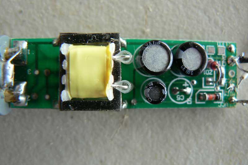
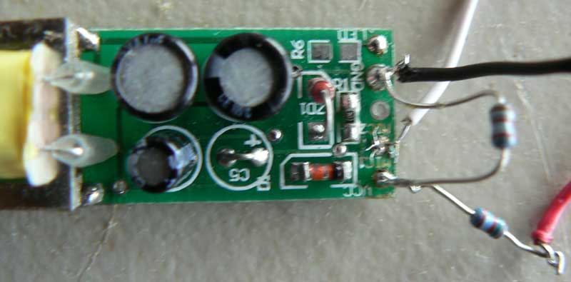
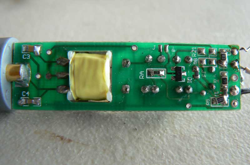
please excuse the hack soldering job, i tried a bunch of different things, and havent decided on the final version yet, your seeing the product of half a dozen hurry-up soldering jobs with a crappy 30w iron.
anyway, i wanted to post the pics, particularly for mshilarious, as im interested in the effect of what ive done here, esp in regard to just taking the resistor to ground, which creates an extra current flow. also any comments on the overall circuit design strategy and its implications/advantages/disadvantages for our use, both in terms of sonic quality and power consumption. i know the pics arent the best, but i think if we can figure out generally what the circuit is doing, i can measure resistances etc or read any cap values we need
ideally the transformer would be swapped for one that outputs 9V open loop, maybe swap a resistor or two without adding any components. although i dont know if transformers are a standard size and would fit that cutout int he board.
Also, berhnards simple powering circuit included a 1.5K resistor off a 9v (for two mics, and a 100 uF 'smoothing' capacitor as he described it between the power lead (on the mic side of the resistor and ground)

what is the purpose of this capacitor, and do i need to add this to this power supply.
i emailed bernhard last night and asked him about it, to which he replied "the CMR is not designed for being used with a phantom power. You may connect it that way at your own risk only. The high open loop voltage and the capability of high current peaks lead to a high risk for the CMR being damaged.". so i think its safe to say he's over it.

