UPDATE: Start doing prototype of the case... get dimensions of holes and stuff... drill manually, make corrections, keep notes... do some filing to fix the screwups.
Some notes:
The Motherboard, Switchboard and VU meter PCBs... crammed in a 2-inch high, 6" width case. As you can see, it is tight... the switches and capacitors have literally millimeter clearances from hitting the ceiling and bottom of the internal case. The distance between the motherboard and switchboard perfectly aligns with the PCB slot of the case.
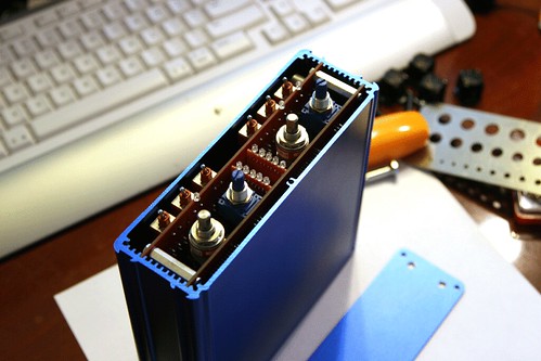
Attach the front panel to the PCBs. Check out the input transformer peeking from the side.

Photo of the blue anodized case with the black anodized rack handles temporarily attached.
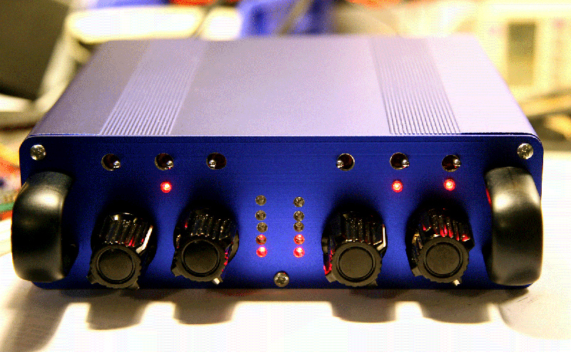
The switch toggle handles peek out just enough... No accidental flipping of switches. It takes some effort to consciously flip it. Using your thumb and fingernails seems to be the easiest way to toggle it. I need to make the switch toggle openings narrower but longer, instead of round.
The blue anodized finish of the case gives it a weird effect when photographed... kinda like a soft glow coming from the surface of the case.
Forgive the crooked holes for the VU meters, and too large holes for the switches.

These were manually drilled.
I'm going to finalize the dimensions, and have a prototype shop do a sample panel for me using CNC.
 Topic: New TS-2 Preamp ... under development (part II) (Read 172603 times)